
Build Page: 1 2 3 4 5 6 7 8 9 10 11 12 13 14 15 16 17 18 19 20 21 22 23 24 25 26 27 28 29 30 31 32 33
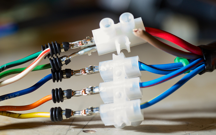
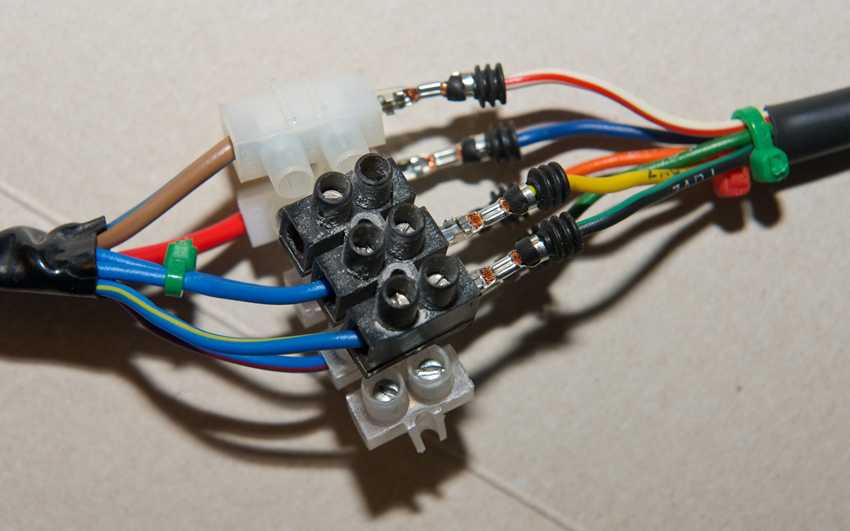
Day 32 - 13-1-14 - My good friend Shaun who is a qualified electrician had given me directions how to connect up the loom to the KTM ignition switch. As my electrical knowledge is non existent I followed it to the letter using some block connectors. I plugged it into the loom and tried it out.
I could see the instrument backlights were on, but nothing else seemed to work. After about 15 seconds from turning on I could smell burning, then some smoke appeared from the connection at the loom. Ooops! That's not good and I immediately turned off and disconnected. Looks like I need to get Shaun back, because I haven't a clue.
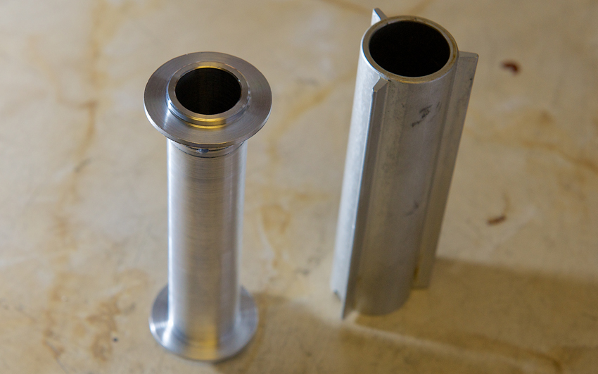
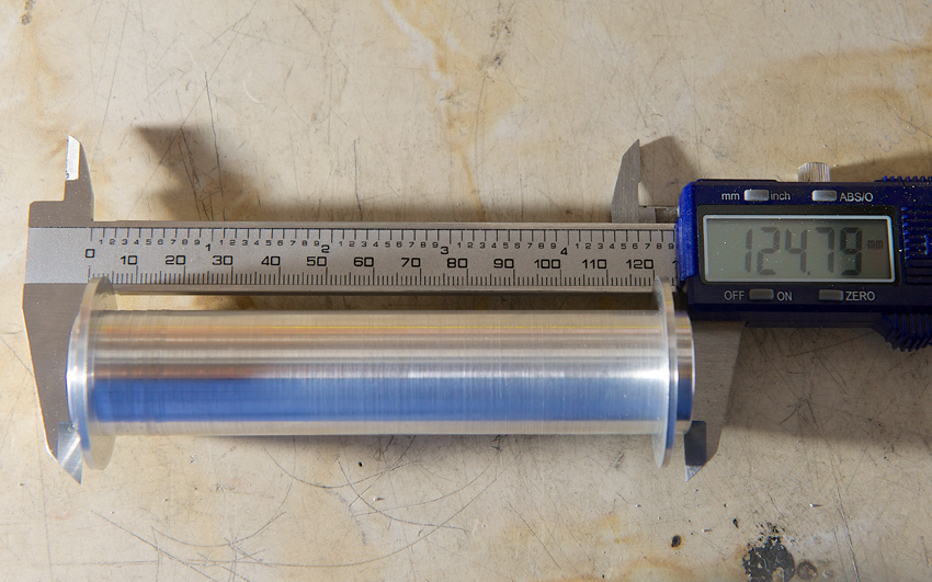
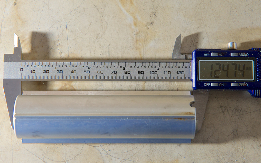
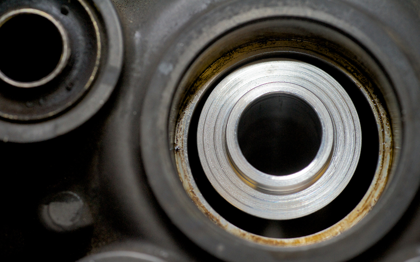
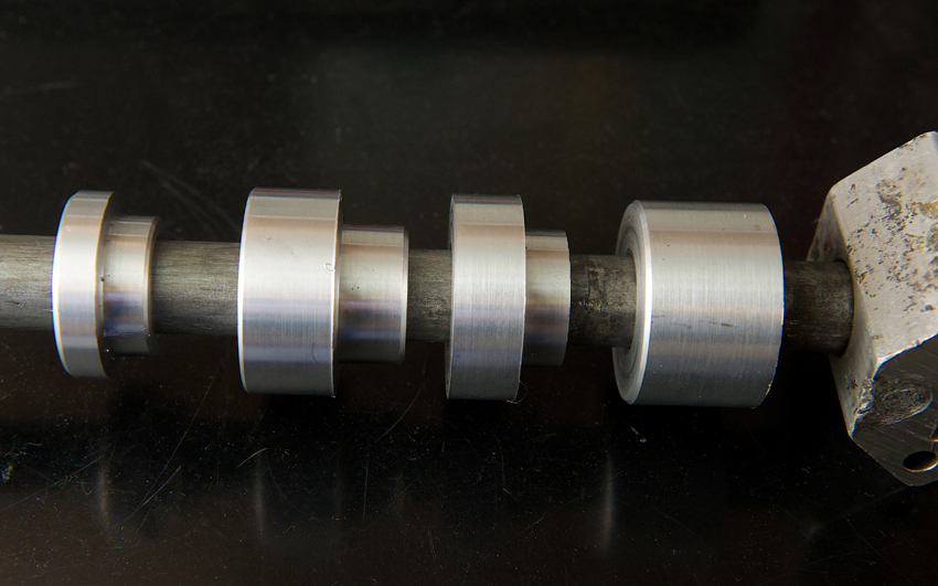
Day 33 - 15-1-14 - After what seems like forever I was finally back at college last night and could finish the internal spacer for the rear wheel bearings. It's not perfect with regards to finish, so much so that my tutor commented that I had a VERY fine thread on the shaft of the spacer. I understood this mickey take immediately, as he was referring to the fact that I hadn't got a dead smooth finish. I would like it to have been perfect, however it will live in the hub between two bearings never to be seen by anyone. What I was pleased about was the fact that my replacement was only 0.05mm longer than the OE one. I can live with that.
You will note that the design is different to the OE one. I couldn't replicate the OE one with my current machining ability, so this is a design that another of my mates came up with. So big thanks to Mike for that.
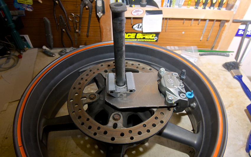
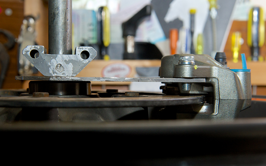
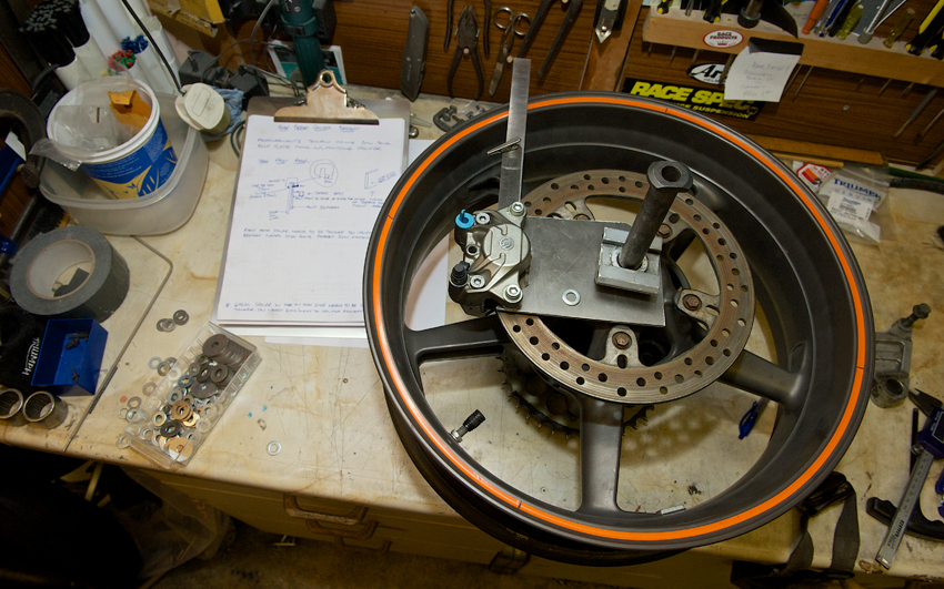
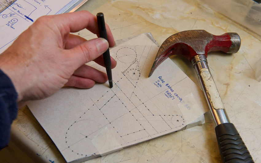
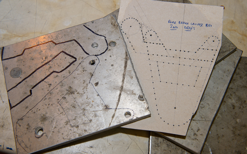
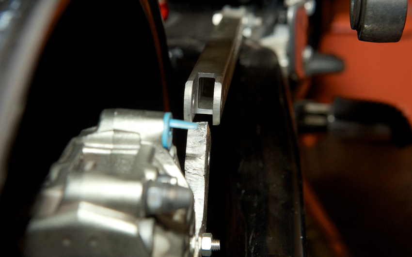
I also had a go at mocking up the rear brake caliper bracket using a piece of 3mm thick aluminium. At this stage I just wanted to ensure that I got the holes for the caliper positioned correctly in relation to the axle hole, before moving on to designing the caliper. I was pretty much spot on, so was chuffed with that.
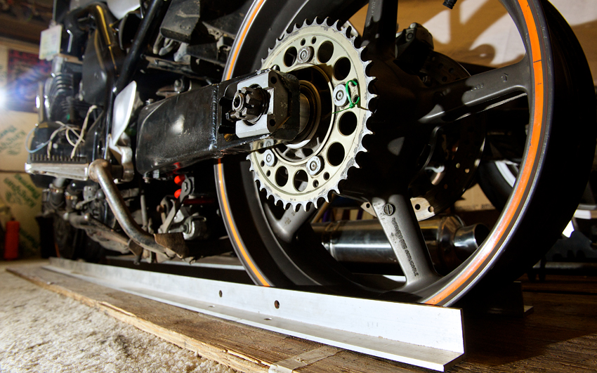
Day 34 - 16-1-14 - Got the rear wheel bearings in today. Did the old trick of putting the bearings in the freezer overnight and then heating the hub with a heat gun. Previously I've used a hair dryer for this, but still ended up having to hammer the bearings into place. That doesn't feel nice. If you've not heard of this, the idea is the bearings contract in the cold, ever so slightly and the hub expands in the heat, ever so slightly, making bearing insertion easier.
I wasn't holding my breath. Once one side was done I got a bearing from the freezer. I lined it up as level as possible before I reached for the hammer and drift. As I let go of the bearing I expected it to sit in the opening. Nope. It just dropped straight down into position. No way! How happy was I? I couldn't believe it. I made sure it was in position then turned the wheel over. This is the important bit if you are to avoid much swearing. Make sure to put in the wheel spacer before fitting the second bearing. Done.
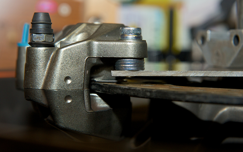
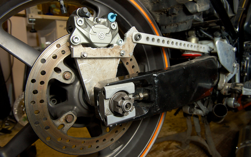
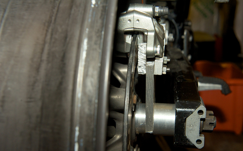
Further disbelief followed as the bearing on the other side dropped into place as easily as the first. Result. Now I could carry on with measuring up for the rear brake caliper using washers to space out the caliper to the correct point, as the 5mm thick disc only has a 7mm wide channel to run in. So I needed clearance of 1.5mm on either side of the disc. Not much room for error and obviously critical to get it right. Pretty confident with my measurements.
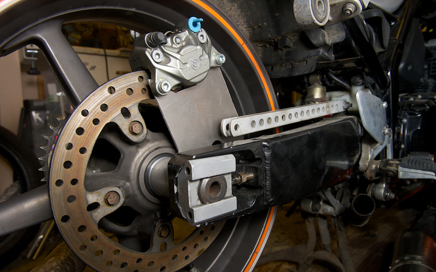
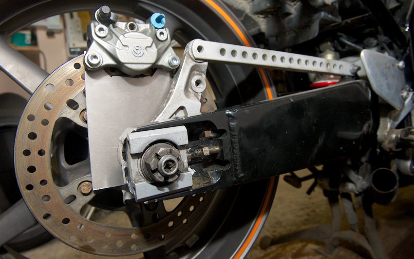
Day 35 - 17-1-14 - Carried on with the caliper bracket. Now I used the OE Fazer bracket to help me determine where the hole for the torque arm needed to be placed.
Day 36 - 18-1-14 - Back to the ignition wiring. Shaun had a good look at the wiring diagrams and spotted that the diagram I had given him for the Fazer didn't tie up with the wire colours actually in my bikes loom. He did an internet search and came up with the correct one. The smoking wires was because I had unwittingly given him the wrong information. DOH! He came up with a completely different set up which I'm glad to report worked perfectly. Thanks Shaun, I can now use the KTM ignition switch.
Back to work on the brake caliper bracket. Confident my measurements are correct I purchased some 10mm thick aluminium plate and made a template to mark out the shape. On some good old Corn Flake packet yet again. Guess what my favourite cereal is? Once done I decided on the lazy cutting out route of the plasma cutter at college. I've only used it once before, but it's a fantastic bit of kit. It literally cuts through metal like a hot knife through butter. Oh the power!
On the day of the evening I was going to college to cut out my bracket I realised I needed to redesign it. That was a bit last minute dot com, however just glad I realised it before wasting metal.
Day 37 - 27-1-14 - With a rather rough looking test bracket I found I was out by about 1mm as the disc was rubbing against the caliper. An easy fix, I just need to make the wheel spacer 1mm wider to push the bracket outwards. The mount for the torque arm also needs to be about 2mm further out.
Day 38 - 1-2-14 - I made new wheel spacers last Tuesday at college, taking into account the need to move the brake bracket out by 1mm. I used the 50mm thick round bar made of 6082 T6 aluminium and managed to get all four done just as the class ended. Glad I'm not paying someone to do this work, it would cost a fortune in labour. Well at least at the pace I work at!
Speaking of getting someone to make things for me. I realise the brake bracket is not something I can make as I don't have enough time left on my course and there is no time left to teach me how to use a milling machine. Bit disappointed about that. So I may have to look at getting one made on a CNC machine. I think I'll get in touch with Harris Performance as those boys have MotoGP experience and know exactly what they are doing. Hope it won't be too expensive.
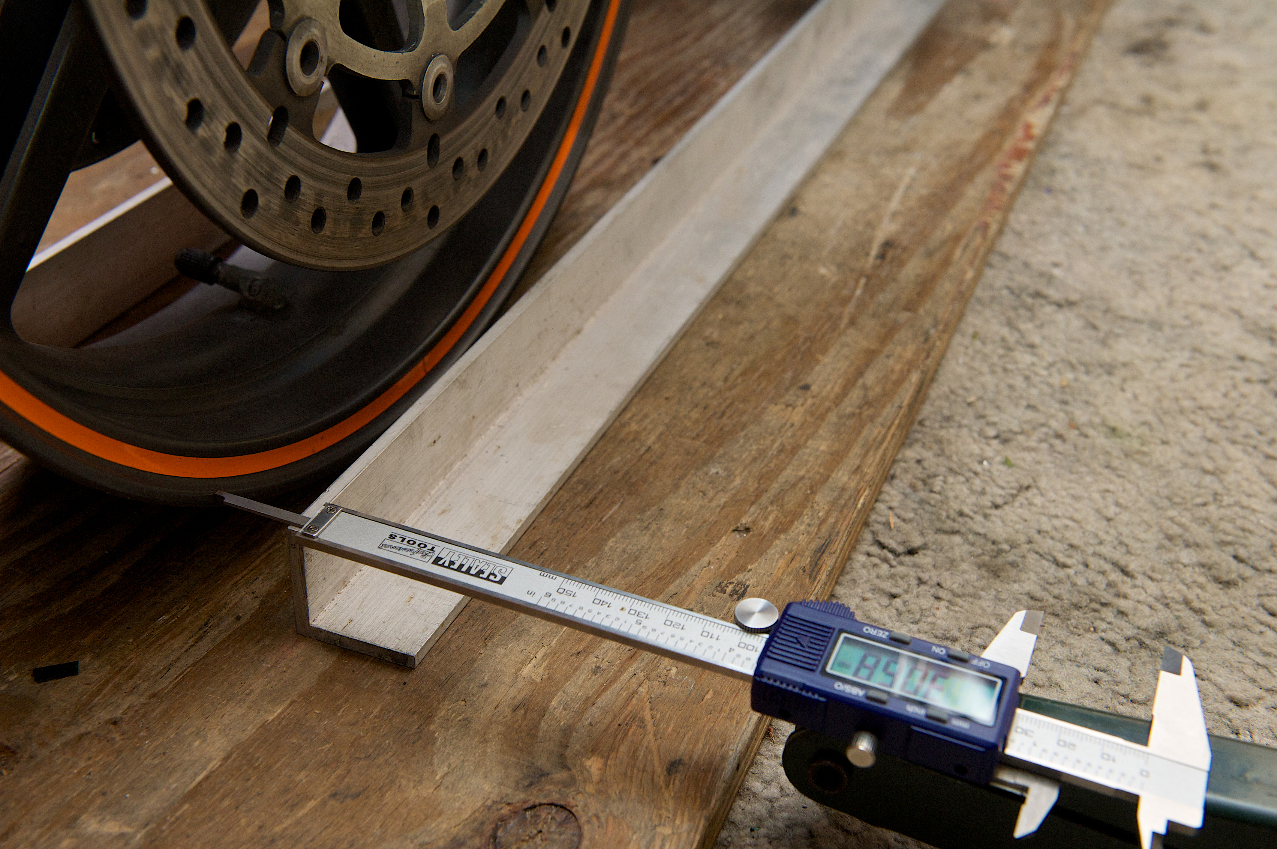
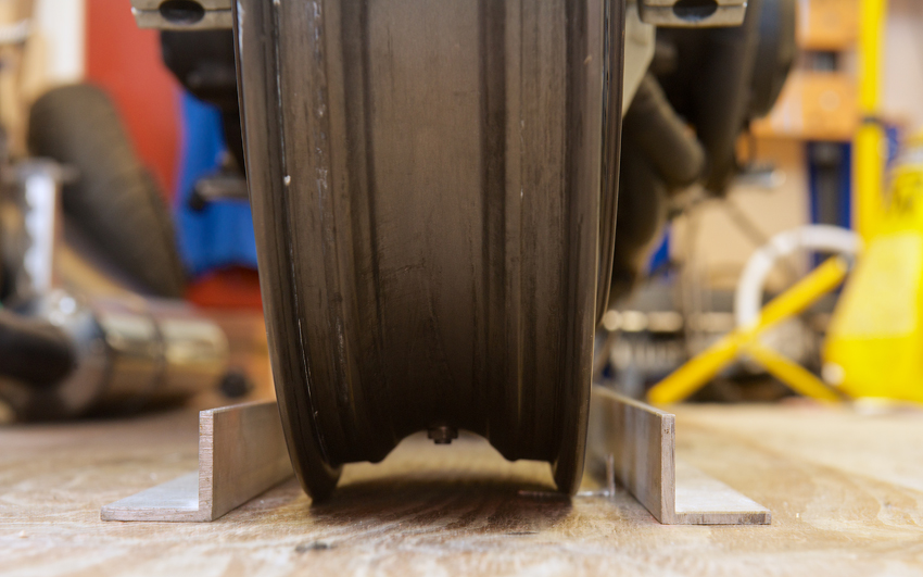
Day 39 - 3-2-14 - Some time ago I'd managed to confirm that the front and rear wheels were aligned. Now when I checked they weren't! Was it the new spacers I'd made? Pretty sure they were correct. It was driving me mad, so I slept on it. It dawned on me that I hadn't torqued up the swing arm pivot bolt, so I did that. The front end was all tightened up correctly.
I had the rear wheel just pushed all the way back in the swing arm and tightened up correctly. I thought maybe I should use the adjustment marks cut into the swing arm. I did that and checked again. Now that's better. After much subtle adjustment of the front wheel direction I got it to be be between 1.1 and 1.5mm off centre to the right hand side. I don't know how critical that measurement is, although it should ideally be perfect I would think, but that doesn't seem too bad to me. Lets not forget this bike has had a front end impact, so there is still a chance the frame has a slight bend in it. Once I strip the frame down I should have a better idea.
If you would like to receive an email update when the next instalment is published then please email me at rubyracing@hotmail.co.uk putting "Project Ruby Racer Updates" in the subject box. Don't worry I'm not going to spam you, you will only receive an email whenever I update this site.
Build Page: 1 2 3 4 5 6 7 8 9 10 11 12 13 14 15 16 17 18 19 20 21 22 23 24 25 26 27 28 29 30 31 32 33
*
 |
 |
 |
 |